Adding auto-leveling to CNC USB Controller

June 10, 2018 Maker

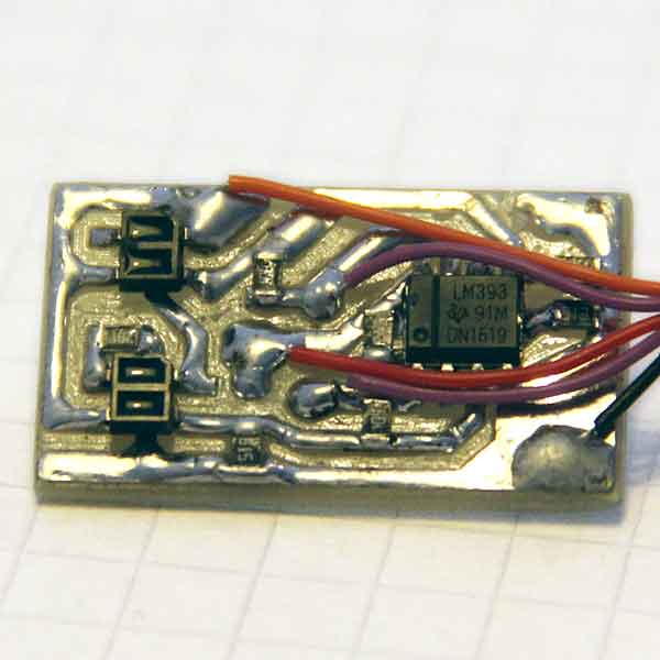
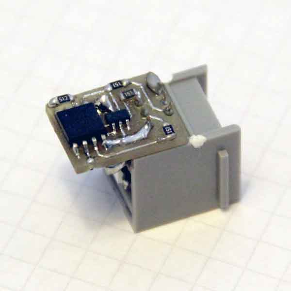
In my previous post, I mentioned that my 3020 CNC allows my make circuit boards like the ones below, which requires accurate control over the cut depth. In this post, I’ll go deeper into how I achieved this level of control using some software I wrote.

Limits to leveling

As mentioned before, getting the cut depth just right when using V-shaped engraving bits is essential. Too shallow, and the traces won’t get isolated from each other. Too deep and you’ll quickly end up with dull bits and with torn or overly thin traces.

In its most basic form, the cut depth can stabilized from location to location by first milling a flat area into a waste board before the copper-clad circuit board is stuck onto it. This removes any major misalignments between the axes and the bed. However, the copper layer’s height may still vary too much for V-carving as the copper-clad board (or adhesion layer) may vary in thickness or may be curved.

Auto leveling

Auto leveling is a process that tries to compensate for height differences instead of trying to prevent them. First, the CNC is used to probe the local height of the PCB in lots of places. Then, these probed heights are used to adjust any G-Code path such that they curve along with any detected imperfections.

Probing the height of a PCB locally is typically done by slowly lowering an end mill until an electric connection is made between the end mill and board’s copper layer. Getting this to work was easy for me as my CNC machine came with both the necessary hardware and software to do this. However, probing over a grid and then using this to distort G-Code to do auto-leveling was unsupported.

Obviously, I could’ve bought better electronics and software. But being a software developer, I had other options as well. In turns out that CNC USB Controller, which is the Windows control software my machine came with, can be controlled through command-line arguments as well as through a COM interface. This makes it possible to add support for auto-leveling using my own external applications.

My toolset

Here’s an example of the resulting process:

At the beginning of this clip, I’m starting my command-line tool called cnc_warp_probe. The used command-line arguments tell it to probe an area of 40 x 40 mm using 4 x 4 measurements. In turn, this tool makes CNC USB Controller take the individual measurements at all the right locations, and stores the collected probe data into a text file. When it finished probing at all 16 different locations, I then copied the G-Code onto the clipboard and called code_warp_gcode_clipboard.bat. This feeds the probe text file and the G-Code on the clipboard into a second tool called cnc_warp_gcode. This second tool takes the probe text file, fits a quadratic surface through it, and uses it to vertically adjust the G-Code. The .bat file then puts the adjusted G-Code back onto the clipboard, after which I complete the procedure by pasting that into CNC USB Controller again.

These tools have been very useful for me, and I’ve made them open source so that anyone can use them freely. Please do understand that this is just a hobby project, so I do not offer any guarantees or support, nor do I accept any kind of liability. Links to the source code and the binaries are below. The code has been written in C/C++, so anyone comfortable in Visual Studio should be able to build and extend it in any way they want. Enjoy!

Downloads

  • Tool binaries [ZIP]. Last updated on Jun 16, 2018.
  • Tool source code [Bitbucket]. Last updated on Jun 16, 2018.

Previous post: CNC-ing different materials (June 5, 2018)
Next post: Reducing noise and dust (June 24, 2018)

Comments (27)

Darren
April 5, 2019

Thanks for this, unfortunately it doesn’t work on my version of the software (SW 2.10.1208.601), I get an error trying to register the DLL.

RegAsm.exe “C:\Program Files (x86)\CNC USB Controller\CNCUSBControllerAPI.dll” /codebase
Microsoft .NET Framework Assembly Registration Utility version 4.7.3190.0
for Microsoft .NET Framework version 4.7.3190.0
Copyright (C) Microsoft Corporation. All rights reserved.

RegAsm : error RA0000 : Could not load type ‘TrajBuffer’ from assembly ‘CNCUSBControllerAPI, Version=2.10.1707.1201, Culture=neutral, PublicKeyToken=null’ because it contains an object field at offset 166484 that is incorrectly aligned or overlapped by a non-object field.

I think my version is different to yours, I bought it a few weeks ago. Here’s the directory listing

Directory: C:\Program Files (x86)\CNC USB Controller

Mode LastWriteTime Length Name
—- ————- —— —-
d—– 27/03/2019 16:45 Driver
d—– 27/03/2019 16:45 Samples
d—– 27/03/2019 16:45 Scripts
-a—- 08/08/2012 01:28 8664576 CNCUSBController.exe
-a—- 27/03/2019 16:45 4667 CNCUSBController.keys
-a—- 27/03/2019 16:54 249 CNCUSBController.lic
-a—- 17/12/2011 23:21 3223299 CNCUSBController.pdf
-a—- 05/04/2019 14:16 33923 CNCUSBController.setting
-a—- 05/04/2019 13:13 33988 CNCUSBController.setting.bak
-a—- 05/04/2019 13:19 3027 CNCUSBController.var
-a—- 02/04/2019 21:53 3027 CNCUSBController.var.bak
-a—- 10/07/2017 16:04 251560 CNCUSBControllerAPI.dll
-a—- 27/03/2019 16:57 16286 unins000.dat
-a—- 27/03/2019 16:57 1174979 unins000.exe

Didier
July 27, 2019

Hi,

Thanks for your soft.
I’m testing currenlty.

My CNC is home made and the hard controller is an Eleksmaker IVAxis.
I did not configure the limits in CNC USB controller and did not connect a probe.

With your sample : >cnc_warp_probe.exe probe_measurement.txt 0 0 40 40 1000 4 4 1

I see the X / Y moving but not the Z.

Did you have an idea if I have to configure something first into CNC USB Controller to have your program working ?

Tx in advanc,

Best regards

Didier

Didier
July 27, 2019

HI,

I found into the CNC USB Controller (since is like a MK1 board) ..

many thanks !

it’s works ;)

Stevan
February 17, 2020

Big thanks!

I know even small beer is better but how :)

Just for users who have custom settings of the cnc with custom settings name it is better to rename it to CNCUSBController.setting, other option is probably to change it in the code and than to build.

Also for me it was the easiest way to “connect” dll-s to put cnc_warp_probe.exe in the usb cnc instalation folder (c:\Program Files (x86)\CNC USB Controller\)

once again thanks for great work

Giliam
February 19, 2020

Thanks for the tips, Stevan

makmak
March 8, 2020

Hi,
Surface estimation rel. to last probe:
0, 0: 103.79 -> err: -0.216112
13.3333, 0: 103.13 -> err: 0.362805
26.6667, 0: 103.565 -> err: -0.382406
40, 0: 102.993 -> err: -0.349739
40, 13.3333: 102.69 -> err: 0.206944
26.6667, 13.3333: 102.77 -> err: 0.550788
13.3333, 13.3333: 103.198 -> err: 0.317509
0, 13.3333: 102.8 -> err: 0.681104
0, 26.6667: 104.85 -> err: -1.07805
13.3333, 26.6667: 104.85 -> err: -0.928159
26.6667, 26.6667: 104.295 -> err: -0.452389
40, 26.6667: 102.832 -> err: 0.702257
40, 40: 104.985 -> err: -0.429811
26.6667, 40: 104.853 -> err: -0.104945
13.3333, 40: 104.075 -> err: 0.636795
0, 40: 103.963 -> err: 0.483411
ERROR: GCode not specified (everywhere) in millimeters. This will probably lead to incorrect results

what is the reason for the error?Thanks.

Giliam
March 9, 2020

Hi makmak. That means that some settings in the gcode are set in inches. I never bothered writing support for imperial units, so if possible, try setting your gcode exporter to metric mode (mm) instead of imperial (inch). Good luck

makmak
March 9, 2020

Hi,
it was already in metric mode.

It measures the whole area with a probe but cannot create some kind of file. It gives the above error.

Giliam
March 10, 2020

Hi makmak. It should mean one of two things: (1) There’s neither a G20 nor a G21 in your GCode (so it leaves the units unspecified, which is invalid GCode in general), or (2) there’s (only) a G20 in your code which puts it in inch mode, which isn’t supported. Hope its the first then, because adding a G21 at the top of your code will then probably fix it. If its the second, then there’s something weird going on if you say its in metric mode.

makmak
March 10, 2020

g code;

G21
G0Z10.000
G0X0.000Y0.000
S12000M3
G0X-1.000Y4.000Z2.000
G1Z-1.000F1200.0
G1Y56.000F3600.0
G2X4.000Y61.000I5.000J0.000
G1X56.000
G2X61.000Y56.000I0.000J-5.000
G1Y4.000
G2X56.000Y-1.000I-5.000J0.000
G1X4.000
G2X-1.000Y4.000I0.000J5.000
G0Z2.000
M5
G0Z10.000
G0X0.000Y0.000
M30

makmak
March 10, 2020

examples g code
can you show me?

makmak
March 10, 2020

WHICH PROGRAM DO YOU CREATE G CODES?

Giliam
March 11, 2020

I used to let CNC USB Controller make the final g code based on the gerber file I imported. I don’t have any g code file lying around here. Maybe its a line ending issue in your file. If you share a link to your file, I can have a look.

nishizu
March 29, 2020

Hi Giliam, i’m sorry to bother you, but i’m stuck…i have the same issue Didier is having: z axis is not moving while probing. He said he solved the issue with some configuration but i cant find the solution. i have set limit- switch and it works (when i do some manual movement the machine stops), but when i use your probe software z axis is not moving :( any help? thank you in advance

Giliam
March 29, 2020

Hi Nishizu. The software is relies on CNC USB Controller to do the Z probe for it. So maybe you haven’t set up CNC USB Controller’s built-in Z probe functionality correctly? In other words, please try to get the Z probe functionality to work from within CNC USB Controller first, and only then try to auto-level with my addition to it. Hope this helps. Regards,Giliam

nishizu
March 29, 2020

thank you very much for your fast reply! i didnt have enabled the “Tool Sensor”…im so dumb! I’ll keep working on it and finish all the configuration! I’ll keep you updated ;)

OneLeggedHorse
March 29, 2020

Thanks for sharing.
Unfortunately this doesn’t work for me neither. Registering DLL gives a warning (not an error tho) and running probing crashes. Instantiating API succeeds but during initialization it crashes.

Giliam
March 29, 2020

Hi Nishizu, I hope that will solve it then. Good luck!

Giliam
March 29, 2020

Hi OneLeggedHorse. Sadly, I only have one version of the DLL, and it might possibly depend on your specific USBCNCController executable. What’s the warning you’re seeing when trying to register?

nishizu
April 2, 2020

It works! Amazing software and superuseful, thank you very much! ;)

Jean-Jacques
April 14, 2020

Hi Giliam,
I haven’t got any CNCUSBControllerLib.dll file in my program file folder. Any idea
Sincerely.

Giliam
April 14, 2020

Hi Jean-Jacques. It’s part of CNC USB Controller in the version I have installed, which is (SW) 2.10.1707.1201. Maybe your version is too old or too new, and you could try to download a different version?
Regards.

Anonymous
April 16, 2020

Thanks in fact I did reinstall it and I got the file but my version is too new…. the last one and Planet cnc doesn’t want to send me the old version…. so that look like a dead end.
Sincerely.
J.J.

Jean-Jacques
April 16, 2020

The anonymous was Jean-Jacques sorry

Muhammad Rizwan
January 24, 2021

Hello Sir,
I had bought a chines CNC, whose controller bored number is jp382c, for PCB milling. But unfortunately, because of lake of knowledge regarding Auto leveling feature, I have face failure. Sir I also tried the way you did provided but my ‘CNC USB CONTROLLER’ folder lake the file of ‘CNCUSBControllerLib.dll’ and my SW(2.10.1208.601) which is older then your version as you had mentioned in your comments.
Sir, with Great respect if Possible can you please help me out with this problem.

phongnh
December 20, 2022

some of my experiment work with auto-leveling by Giliam
1. you should place the .exe file (file probe_measurement & wrap_code) in the usb cnc instalation folder (c:\Program Files (x86)\CNC USB Controller\).
2. I use Windows PowerShell run at adminnitration mode on Win 10 to put command code. First, I run (cd “c:\Program Files (x86)\CNC USB Controller\”) to change working directory. After, config “Z limit -” and get (GND, Z-) pin to make the probe, run ( .\cnc_warp_probe.exe probe_measurements.txt 0 0 250 250 1000 5 5 1) to generate probe_measurement.txt file.
3. I use ArtCAM export gcode_input.txt(must export follow format Bodcad_mm.agc), and copy gcode from .agc to .txt
4. Finally, wrap code by run (./cnc_warp_gcode.exe probe_measurements.txt gcode_input.txt gcode_output.txt)
=>i see the z of gcode to be wrap, it’s wonderful, tks author a lot :v

phongnh
December 20, 2022

notice is put G21 in the top of the file “gcode_input.txt”

Leave a comment