Precision and accuracy
Now that my 3020 CNC is working properly, I can start to put it to good use. Obviously, my 3020 is limited in size and power, and expects you to work with or around its limitations. The precision of this machine when repeating the same movement over and over is acceptable for most purposes. I’d roughly estimate the error at less than 0.05 mm (2 mil) between runs. But even though the difference between runs (i.e. the repeatability error) is acceptable, the absolute error each of these runs produce (i.e. the accuracy error) can be significantly more because of flex in plastic frame.
As the frame flexes more when the spindle exerts more force, the accuracy of the machine can be improved by limiting the feed speed and cut depth. So even though it can move at over 600 mm/min, I typically limit the feed speed to 200 mm/min if accuracy is important. Nevertheless, when trying to mill deep into harder wood for example, it seems to be impossible to get an absolute error smaller than 0.5 mm (20 mil) at any speed. This is probably why it’s advertised as an engraving machine instead of as a router.
It is possible to largely compensate for absolute accuracy errors in the CAD drawing and/or tool setup because the flex is fairly symmetric and predictable. But the more accurate you want the result to be, the more iterations you may need to get it right (which may be costly and time consuming).
LEGO
One thing I’ve been working on is my own alternative to LEGO Mindstorms, making my own sensor and actuator bricks and software interface. I’ll leave the details for another post, but I’ve been using this cheap machine to both modify existing LEGO bricks, as well as create my own LEGO-compatible bricks.
Modifying existing LEGO bricks is relatively easy. For ease of clamping and repeatability, I glued a LEGO plate onto my waste board, and simply pressed the brick I wanted to modify onto this, together with some bricks to surround it. At a low feed rate and cut depth per pass, this was enough to keep the brick in place during milling.
LEGO bricks are made out of ABS plastic which becomes quite sticky when its temperature rises. Consequently, it can start to stick and wrap around the whole end mill if not handled with care. I used a thin corn cob end mill, which is probably not ideal for this type of work, but it did the job as long as I kept it moving and kept spraying a bit of oil on it once in a while.
-


- Milled brick, PCB and plate

-

- After assembly

-

- Corn cob end mill
To mill my own hollow LEGO bricks from scratch, I mill the individual faces out of sheet material and then glue those together. At first, I used plexiglass sheets but that stuck to end mill even quicker because it has a lower glass temperature than ABS. I then switched to using polycarbonate sheets, which is both tougher and harder to melt than plexiglass and ABS.
To model the bricks, I’m using Autodesk Fusion 360, which is free for hobbyists. The four side walls are designed to be made out of 1.5mm thick sheets and contain rabbets to simplify exact assembly as well as increase the surface areas for the super glue. Both the bottom and top face are milled out of 3.0mm sheets.
-

- CAD drawing of faces

-

- Render of the faces

-

- Assembled result fits perfectly

It’s important to get the studs and anti-studs just right so that they fit perfectly together with other bricks. To get to the necessary level of accuracy, I had to do a number of iterations on the CAD drawing to compensate for the errors introduced by the flex in the frame and the flex in the thinner polycarbonate areas. This is why the dimensions for the (anti-)studs in the CAD drawing above are slightly off compared to the official brick dimensions. Finding the dimensions that worked best was a relatively quick process because I designed the faces parametrically (i.e. they were modeled using constraints).
Circuit boards
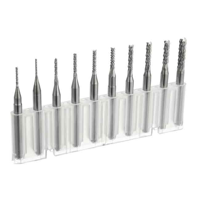
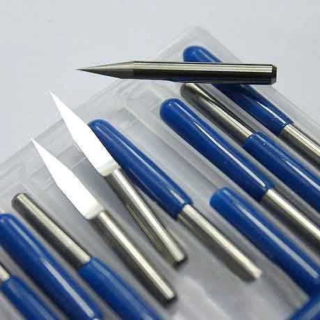
Another thing I’ve been using this machine for is milling circuit boards. Obviously, it’s fairly easy to just order PCBs online but then you still have to wait a while to get them. It’s also possible to etch them chemically, but then you still have to drill and cut them using some other method. With a CNC, it’s possible to start with a fully copper-clad board and remove all copper that isn’t part of the design using a thin V-shaped cutter bit, and then drill and cut out the board using a regular end mill, all on one machine.
-

- V-shaped PCB bits
-

- Copper clad boards

-

- After milling, drilling and tinning

Copper-clad FR4 boards consist of a tough fiberglass & epoxy plate with a copper layer on top that’s less than 0.1 mm thick. Consequently, cutting much deeper than 0. 1 mm will wear down the cutter’s tip a lot quicker than necessary. To get the best possible basic control over the cut depth, I used to mill a flat plane into a fixed waste board, and then stick the copper-clad board onto this perfectly flat plane using thin double-sided tape. Getting this leveling right is even more crucial when using V-shaped bits because the cut depth will then also affect the final trace width. The V-shaped bits I use are typically 30 degrees and 0.2 mm at the tip. Any finer tip breaks too easily in my experience.
To get even better local control over the cut depth, you need something called auto leveling. This isn’t normally possible with these machines, but in the next post I’ll share some software I wrote to get this to work with a USB CNC Controller-based system nevertheless.
Previous post: Getting into CNC (May 25, 2018)
Next post: Adding auto-leveling to CNC USB Controller (June 16, 2018)